First, let's just give kudos to microwaves101.com. They ain't been slack, and they are definitely awesome!
Setup
To be fair, I was told:
"Pick a project."
"Don't do the coupler."
"Most people pick the other ones."
We selected the coupler because it looked interesting and it was the road less traveled. We chose Altium for the layout work because we thought the skills we would learn would be valuable. Altium is terrific, but so are other programs (as we later learned). Shout out to Eagle, and PCB123 for those in the PNW who work with Sunstone Circuits (great people, great help, really really good at what they do).
Design Criteria
Project Requirements
• Choose one from: Wilkinson Divider, Branch-line Coupler, or Directional Coupler
• 1.5" x 1.5" square PCB
• 0.030" thick FR-4 board
• Copper only with 1 oz. Copper
• No solder mask or solder
We had 6 weeks to complete the design and submit to our vendor of choice (we chose both Sunstone and a now-defunct fab house in China).
Methodology
Because we were learning as we went along, the layout needed to be done as soon as possible with the best possible information available. Starting with a rough polygon layout from PCB123, and the all-important impedance value of 50 Ohms, the mission had begun. To determine length and width, TXLine was used. The calculation for quarter wavelength is also shown below.
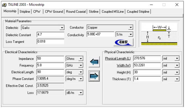
TXLine calculations and quarter wavelength determination
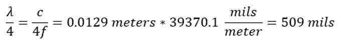
The layout was as follows (using Sonnet Lite and Altium, left to right):
Layout comparison between Sonnet Lite and Altium Designer
That "S" on the Altium side of the image above was tricky. Truthfully, this wasn't solved for initially - the initial layout and four to five hours of simulation (run, adjust, run, repeat) resulted in the final separation distance. Unfortunately this topic was covered formally during the very last week of the class. I did go back and calculate what the separation distance should have been using the guess-and-check method and found that we were fairly close. Only about 2 mils off from our ideal state at 5.8 GHz.
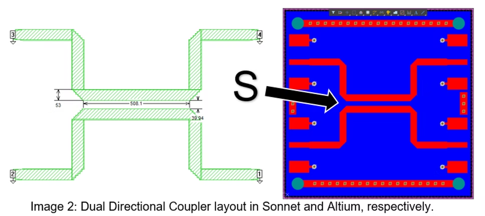
Using the full power of Sonnet, additional configurations were simulated but resulted in less-optimal output. Here are a few of the other layouts that were simulated:
Alternative coupler configurations tested during simulation
Manufacturing Experience
One rule from class was "broken". This being the first experience with RF circuitry, additional samples were desired for experimentation. A *much* cheaper fab house in China was used to order four additional boards. This particular company does not exist any longer, but I'm really grateful for the extra effort to investigate and procure from here. For six dollars, four additional boards were made, apart from the board ordered from Sunstone.
Sunstone was absolutely slammed with work at the time and through no fault of their own were not able to deliver some of the boards on time. *Super* lucky to have stumbled across the other fab house, the only worry was lead time. One of many important lessons learned, a simple email inquiry about where a fab house is in their FR-4 run goes a long way. The ability to take advantage of the end of an FR-4 run with some surplus will significantly speed up your project or help make some different decisions. The stars aligned, and the board was delivered on-time.
Lesson Learned
Always ask for the minimum specifications. When you don't do this step, you get boards back that have mask applied (or not), a different backing material than you expected, and some pretty rough cuts where you might not want them.
Below is the best of what was received, with some added soldering fun for good measure (the connectors were NOT done by me, but by a good friend of mine).
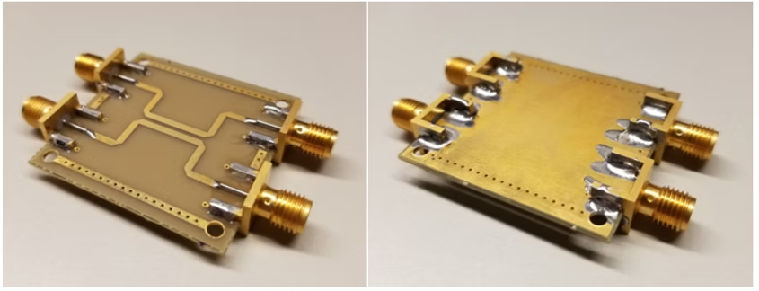
Final PCB with SMA connectors soldered (connector work by a friend!)
Results
After simulating the circuit in Sonnet, a 2-port VNA was used to obtain the S-parameters. After calibration (SOLT!), Coupling, Directivity, Isolation, and Insertion Loss were all measured and compared to the simulated circuit. Only a few of these comparisons are shown here:
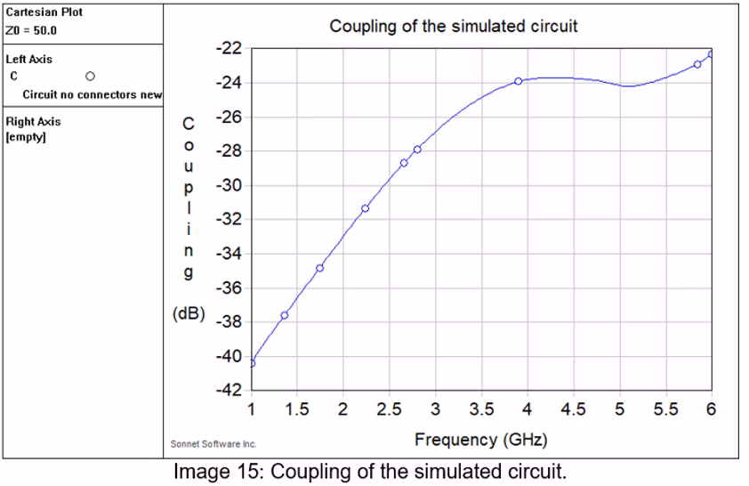
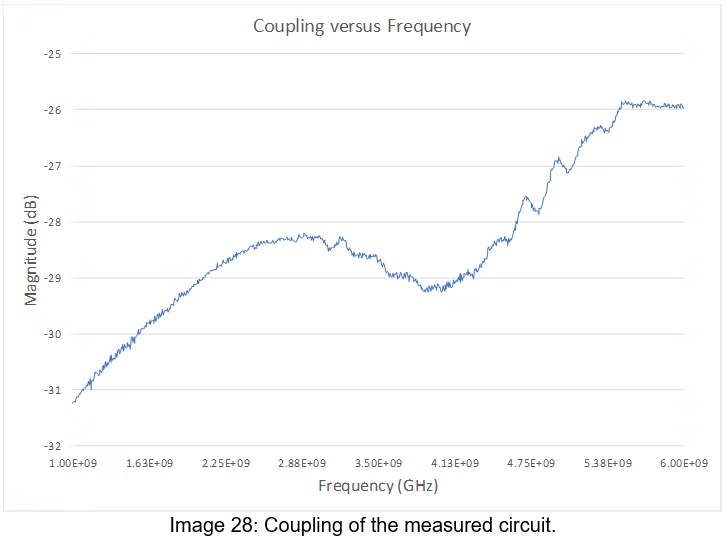
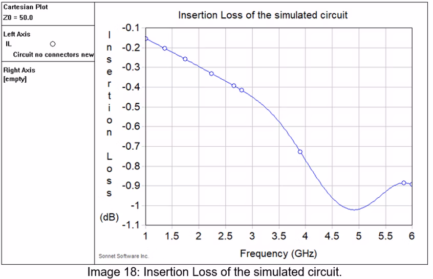
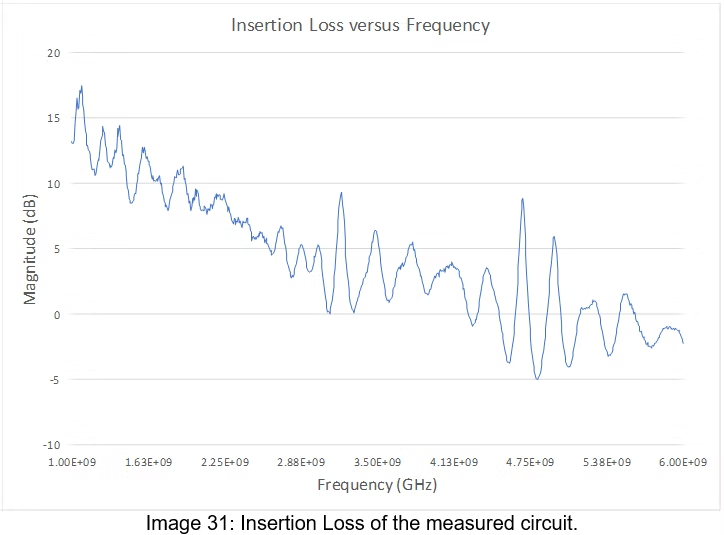
Measurement results: Coupling and Insertion Loss performance
Performance Analysis
From the plots above, the circuit achieved Coupling of approximately -26 dB at the design frequency, while the simulation was fairly close at approximately -23 dB. Practically, this means that the circuit couples a small amount to the coupled port and most of the incident power is passed to the output port. If this was used in real life, it could be a useful circuit if a very small portion of the incident power is needing to be sampled.
On Insertion Loss, the circuit achieved a value of approximately 1.0 dB at the design frequency, while the simulation was somewhat close at -0.89 dB. Practically, not much energy is lost to heat, a result that is expected given there are no active or passive components in this design.
Isolation and directivity were also close compared to their simulations. Measured Directivity was approximately 3.0 dB (simulated 5.5 dB), which is similar to internet searches for a "typical" 20 dB Coupler at the design frequency. Measured Isolation was -26.8 dB (simulated -28.9 dB), another expected result as the circuit does a poor job of isolating the non-coupled and non-through ports.
Improvement Considerations
Considerations for improvement included changing the physical dimensions from square to rounded corners, holding a consistent thickness throughout bends, and tapering connections to the ports would likely change the reflections in a positive way. A better substrate, something like Rogers 4350B, could be used if there were extra dollars to spare for the project.
Cost Comparison
We compared the board from Sunstone to the board from the fab house in China and the results were remarkably similar. The Sunstone board performed very slightly better in all measured ways, but it was more expensive by far.
• China fab house: $28 total for all boards (including connectors!)
• Sunstone board: $168 before connectors were soldered
In all, this was a fantastic experience. The design process, learning how to measure an RF circuit with a VNA, and finding reasonable results was a very rewarding experience.